

ATLAS
ATLAS-3000, the backbone of CALA’s high-intensity laser infrastructure, is a 2.5 PW, 1 Hz Ti:Sa ultrafast laser. It comprises the MPQ’s former ATLAS laser as a frontend, which has been developed by our group over the past 2.5 decades into a 300 TW laser system and complements it with a commercial 90-J amplifier from Thales LAS and a home-built final compressor. The final compressed energy of 70 J and a pulse duration of 27 fs makes it one of the leading Ti:Sa laser systems world-wide, and the world’s highest average-power PW laser system. Its pulses are intended to drive a variety of applications from the acceleration of ions for radiobiology and radiation oncology studies, over ultralow-emittance electronbeams as drivers for medically relevant high-brilliance x-ray sources all the way to studies of nuclear processes and high-field QED experiments. However, in order to drive all these applications on an internationally competitive level, not only raw power is key, but also the pulse-to-pulse stability, beam quality and spatiotemporal contrast of the system have to satisfy extreme demands.
System design and layout:
A schematic layout of the system is shown in Fig. 1:
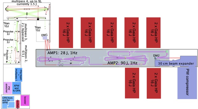
Fig.1: Block diagram of the ATLAS-3000 laser system.
The former ATLAS-300 multi-100 TW laser system serves as the frontend for ATLAS-3000. It consists of two alternative home-built 100μJ-scale short-pulse frontends. The first one, termed “booster”, directly amplifies the oscillator pulses, stretched to approx. 1ps, to 1 mJ in a single Ti:Sa amplifier stage, before they are filtered with a saturable absorber and sent to the main stretcher. The other, termed “XPW-frontend”, is a small homebuilt 20 mJ Ti:Sa CPA system, whose 20-fs output is split to create a 50 μJ, temporally clean pulse from an cross-polarized wave (XPW) generation stage, which is further amplified to 150 μJ by using the remaining, frequency doubled Ti:Sa output as the pump in a subsequent fs optical-parametric amplifier (OPA) stage. Both frontends can seed the main laser chain, but the unexpectedly good performance of the simple booster system has so far prevented widespread use of the more complex XPW/OPA setup.
After being stretched to approx. 800 ps in a commercial Oeffner stretcher the pulses are further amplified to 0.5 mJ in a ring regenerative amplifier with active spectral shaping and to 20 mJ in a subsequent 5-pass multipass amplifier (multipass 1). These three building blocks consist of slightly modified commercial systems from Amplitude Systems. At the 20 mJ level, the amplified pulses pass a 300-ps rise-time, low-jitter ultrafast Pockels cell to reject ASE and prepulses from the regenerative/multipass amplifier stages. Further amplification takes place in a home-built 5-pass bow-tie amplifier (multipass 2) to 0.5 J with 10 mm top-hat beam size and a 3-pass bowtie amplifier (multipass 4) to 1.5 J with a 37 mm top-hat beam. Both bow-ties use home-built integrating mirrors to smooth the pump profile and yield a spatially homogeneous gain region independent of the pump laser’s beam profile, and use spatially-filtered relay-imaging for the amplified beam. The 3-pass system is operated far below its design output of 9 J by bypassing a previous 3 J bowtie amplifier (multipass 3) that was used in the 300 TW version of ATLAS and by using only one of its 10 J TITAN pump lasers to stay safely below any B-integral limit.
After another spatial filter/beam expander with a 60 mm output beam, the pulses are relayed to the two new final amplifiers AMP1 and AMP2, after wavefront correction to better than lambda/25 rms by a 35-actuator, 60 mm active diameter deformable mirror DM1 (ISP system).
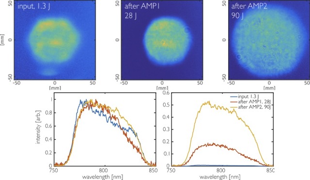
Fig. 2: Top row: beam profiles at the input of AMP1 and the output of AMP1 and AMP2, respectively. The diffraction rings visible in the beam profiles are the result of dust and imperfections on the camera filters. Bottom row: pulse spectra corresponding to the three beam profiles shown in the top row. Left: normalized, right: scaled according to the pulse energy.
This is necessary to avoid the development of hotspots in the beam due to local wavefront curvature during the non-relayed propagation path of approx. 40 m in the final amplifiers. An arrangement of two low-pass reflectors with tuneable angle of incidence act as a reflective spectral filter to suppress the red part of the seed spectrum in order to pre-compensate saturation red-shift in the subsequent amplifiers. Four 16-J Gaia HP 532 nm lasers pump a 90-mm Ti:Sa crystal in the first 4-pass amplifier of the Thales part of the system (AMP1). From an energy level of 1.1 J after the spectral filter, AMP1 boosts the pulse energy to 28 J, before they enter a lens-based apochromatic beam expander telescope and are expanded to the final 90 mm beam size. Ten 16-J Gaia HP lasers pump the final 130 mm Ti:Sa crystal in the 3-pass AMP2 to reach a final energy of 90 J, before a second, 52 actuator deformable mirror DM2 (ISP system) corrects the wavefront aberrations of of AMP1 and AMP2 and sends beam to the final vacuum expander with rms wavefront aberrations smaller than lambda/25.
The near field profiles at the output of multipass 4, AMP1 and AMP2 are shown in Fig.2, together with the pulse spectrum at each of these positions along the beam path, respectively. The home-built vacuum expander uses two reflective off-axis parabolas to enlarge the beam by a factor of three to 270 mm before propagating to the likewise home-built vacuum compressor, operating with two sets of 1480 l/mm gratings, approx. 49 deg. angle of incidence and a grating separation along the central wavelength of 1.03 m.
After the last compressor grating, a 300x420 mm rotating mirror either sends the beam vertically downwards to the beam delivery line or horizontally onto an uncoated wedge and through an uncoated Newtonian telescope to yield an approx. 200 μJ, 3 cm diameter diagnosis beam, which is transmitted through a 1 mm wafer and further relayed and down-collimated to 5 mm beam size, for the diagnostic suite comprising a Grenouille 20 fs FROG (Swamp Optics) and a Wizzler SRSI (Fastlite) device for optimizing the compression, and a TUNDRA 3rd order autocorrelator (Ultrafast Innovations) for checking the temporal contrast over 11 orders of magnitude and up to 2 ns delay (see Fig.3).
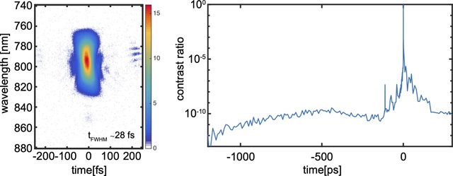
Fig.3: left: FROG trace, right: TUNDRA measurement of temporal contrast
Finally, a third, full-aperture 300 mm deformable mirror with 52 actuators (ISP system) in the beam delivery line corrects the residual aberrations of all optics from the beam expander to the target. It receives its correction information from a homebuilt and online-calibrated Shack-Hartmann wavefront sensor coupled to a long-working distance microscope objective in each target chamber, ensuring a geometric Strehl ratio of typically 95% in focus. Only high-frequency scatter from dust and coating imperfections, as is present to a similar degree in all
real-world laser systems leads to some 15-20 % of the energy to be scattered in a low-intensity Speckle background surrounding the focus, such that the true Strehl ratio is closer to 75-80%. This reduction in Strehl ratio can only be detected by evaluating high (> 105) dynamic range focal spot images, as shown in Fig. 4.
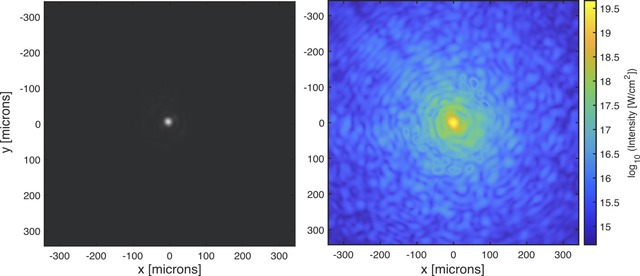
Fig. 4: ATLAS-3000 focus in the ETTF target chamber, focused by an f/20 off-axis parabola. Left: linear gray scale, right: logarithmic false-color image revealing the low-intensity scatter background.
This article is based on [S. Karsch et al. The ATLAS-3000 laser: Description, 1st year of operation and current performance, to be published].